Netlists
The overview provides a simple introduction on how to write netlists. This document will explain in full detail some of its features.
Differences between other SPICE programs
Many SPICE software, like ngspice and LTspice, use/generate netlists very similarly to how they are used in software. There are, however, some important differences:
The first line is NOT ignored. Other SPICE software generally ignore the very first line of a netlist file . This is not the case for this program. Tip: If you want to create a SPICE file compatible with both this software, and other SPICE programs, start the first line with an asterisk. This will make this line a comment, as explained here.
Since the focus for this program is on calculating the solutions as mathematical expressions/equations, and not on actually simulating the circuit, there is no need for most of the “dot commands” other SPICE software include. There is, however, a .STEP command, that works differently from other SPICE software, being used only for difference equations.
Overall characteristics
The spice file follows a very simple structure:
Each line corresponds to a component, in the form
<name> <node1> <node2> <value>, as already explained hereLines begging with
*(asterisks) are comments, that is, are completely ignored by the software.There is a special .STEP command, useful only for when you want the difference-equations for the circuit.
Empty lines and indentations are permitted, if it helps clarifying the circuit.
Components
The only available components for this software are:
Voltage sources
Current sources
Resistors
Capacitors
Inductors
Component names
When writing the component name, the first letter will determine what component it is, accordingly to the table below:
Component |
First letter |
|---|---|
Voltage Source |
V |
Current Source |
I |
Resistor |
R |
Capacitor |
C |
Inductor |
L |
So, for example, V1 is a voltage source, and R_EQ is an resistor.
If you want, you can write the name as partially or fully lowercase (such as Vin, or r_eq) it is recommended however to write every component name in UPPERCASE. This is because, when printing the results, each component/node name will be displayed in uppercase, even if it was written with parts in lowercase in the original netlist.
Nodes
Their names are pretty much arbitrary, so things like 1, IN, V_CC, N1 will work. Try always writing these names
as UPPERCASE if using letters, for the same reason as explained for the component names.
The only name that is not arbitrary is 0, which corresponds to the GND of the circuit. It is always
required (the program will give an error if no node 0 is found in the circuit).
The position you place these nodes matter, because they set the direction of the current, as explained here.
Component values
The values for the components can be written in three different ways: As numeric values, literal values, or as a combination of both.
For numeric values, you can write the number directly (such as 10, 0.005, .04, etc). For numbers that are
too big/too small, you can also:
Use SI Prefixes, where
1500would be1.5kand0.098would be98m. Prefixes going from nano (n) all the way to tera (T) are available.Write them in exponential (scientific) notation, where
123000000would be1.23e8, and0.00000456would be4.56e-6.
The SI units for each value is implicit, related to the component type. So, a resistor with value 2.2k has 2200 ohms.
For literal values, the most important thing about them is that the first letter of the value should be the same as
the first letter of the component name. Other than that, every thing is fair game. So, a voltage source can have a
literal value of VIN, or V1, or even just V. It can’t have a value of, IN`, or any other word that
does not begin with V.
For combinations, you just have to write the numerical value, followed right after by the symbolic one (without spaces
between them). So, some value like 2R1 would be interpreted as “2 times R1”.
Voltage and current directions
The order you write the nodes for each component in the netlist affects the voltages and currents directions for the component. This is specially important for active components (voltage and current sources), since this will determine their polarities, but it is also relevant in passive components, since it will change the sign of its current/voltage (positive or negative).
Active components
Voltage Sources
For voltage sources, the first node is always connected to the “+” side of the voltage source. You can see this below, by the polarities of the voltage sources, and how they are written in the netlist.

V1 IN 0 10
R1 IN OUT 6k
R2 OUT 0 4k
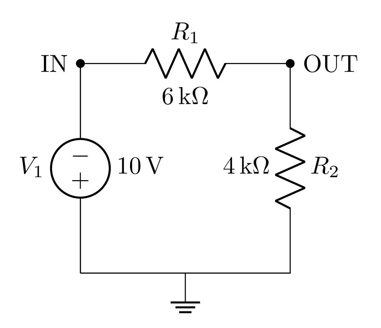
V1 0 IN 10
R1 IN OUT 6k
R2 OUT 0 4k
For the their currents, they will be always pointed out of the first node (similar to current sources). This means that, for the circuit below, the current calculated for the voltage source would be 1 A. If the nodes were reversed for V1 in the netlist, its current would’ve been -1 A.
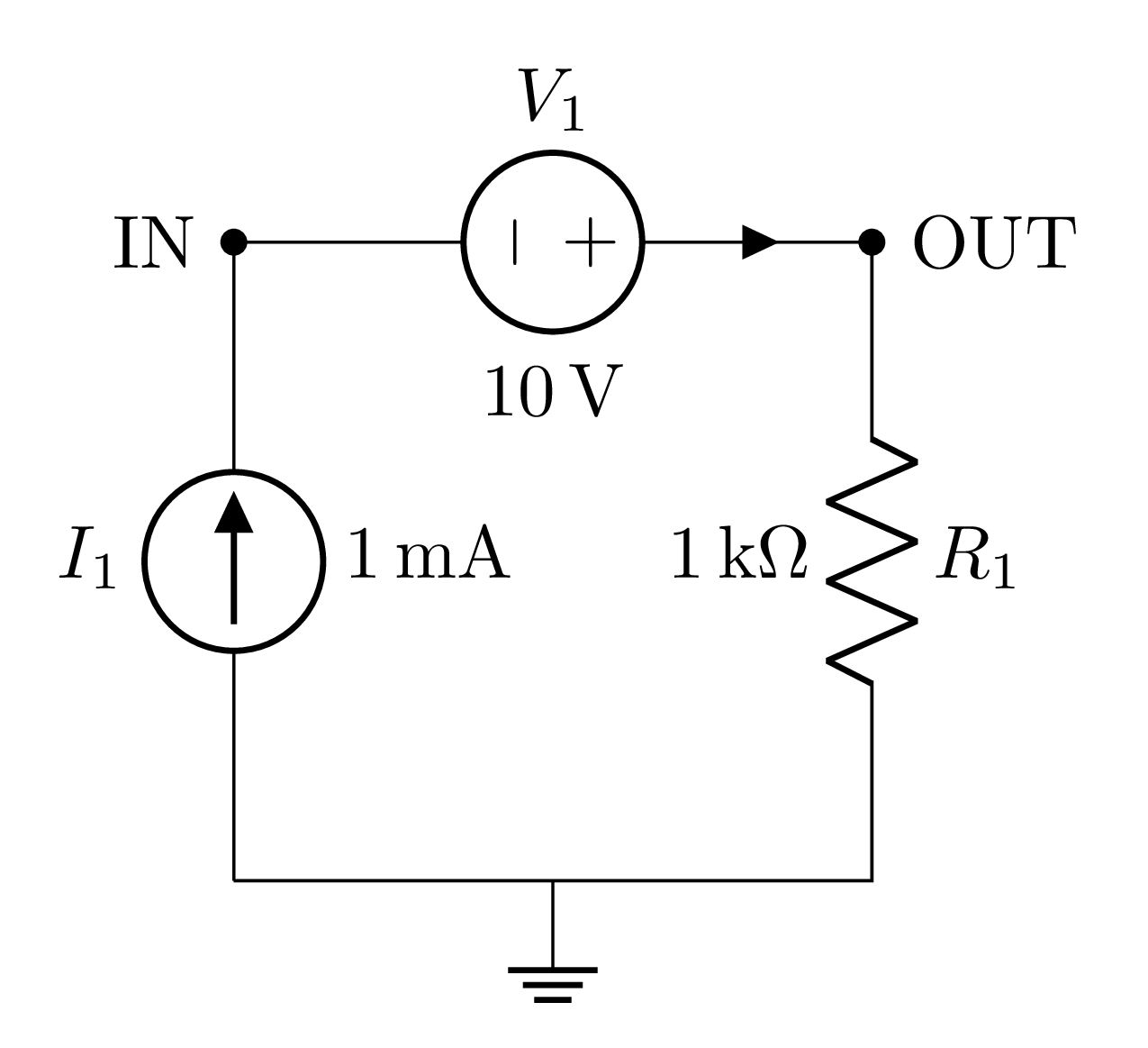
I1 0 IN 1m
V1 OUT IN 10
R1 OUT 0 1k
Current Sources
For current sources, its current will always leave through the first node (entering from the second). You can see this below, by the polarities of the current sources, and how they are written in the netlist.
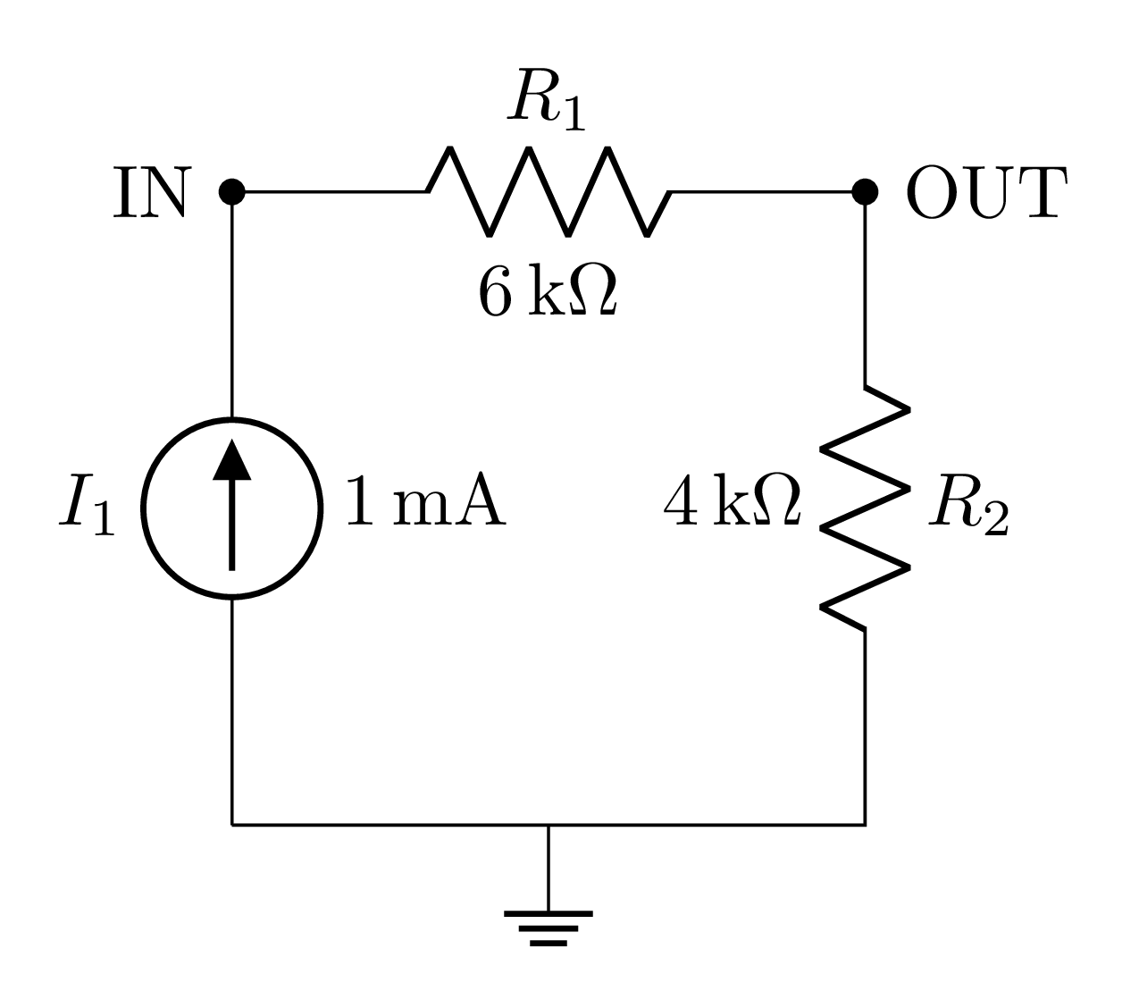
I1 IN 0 1m
R1 IN OUT 6k
R2 OUT 0 4k
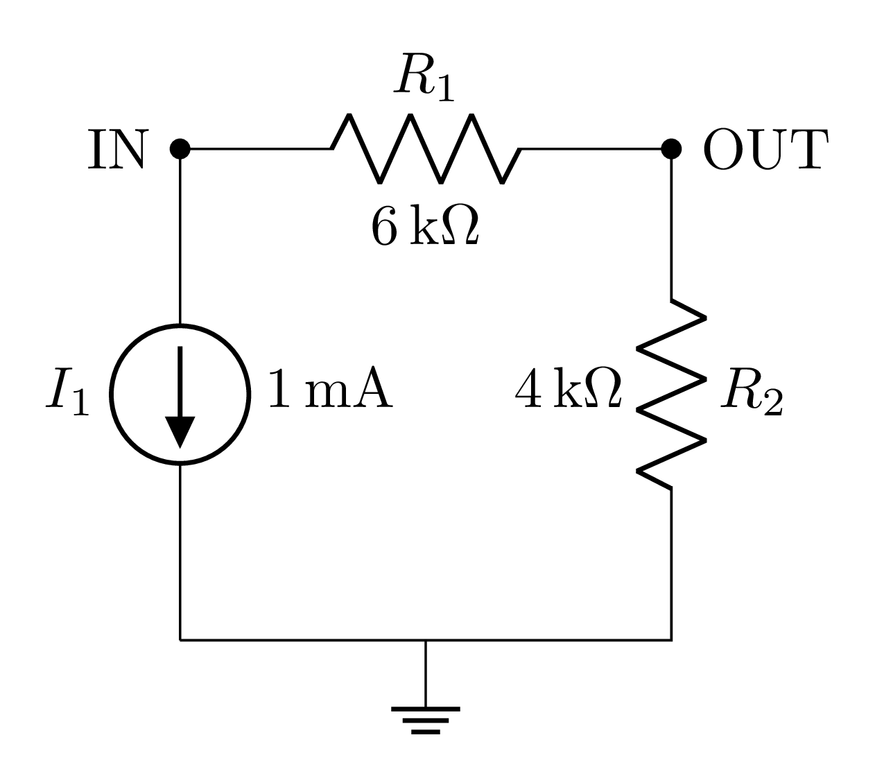
I1 0 IN 1m
R1 IN OUT 6k
R2 OUT 0 4k
For the their voltages, the positive side will always be measured from the first node (similar to voltage sources). This means that, for the circuit below, the voltage calculated for the current source would be 10 V. If the nodes were reversed for I1 in the netlist, its current would’ve been -10 V.
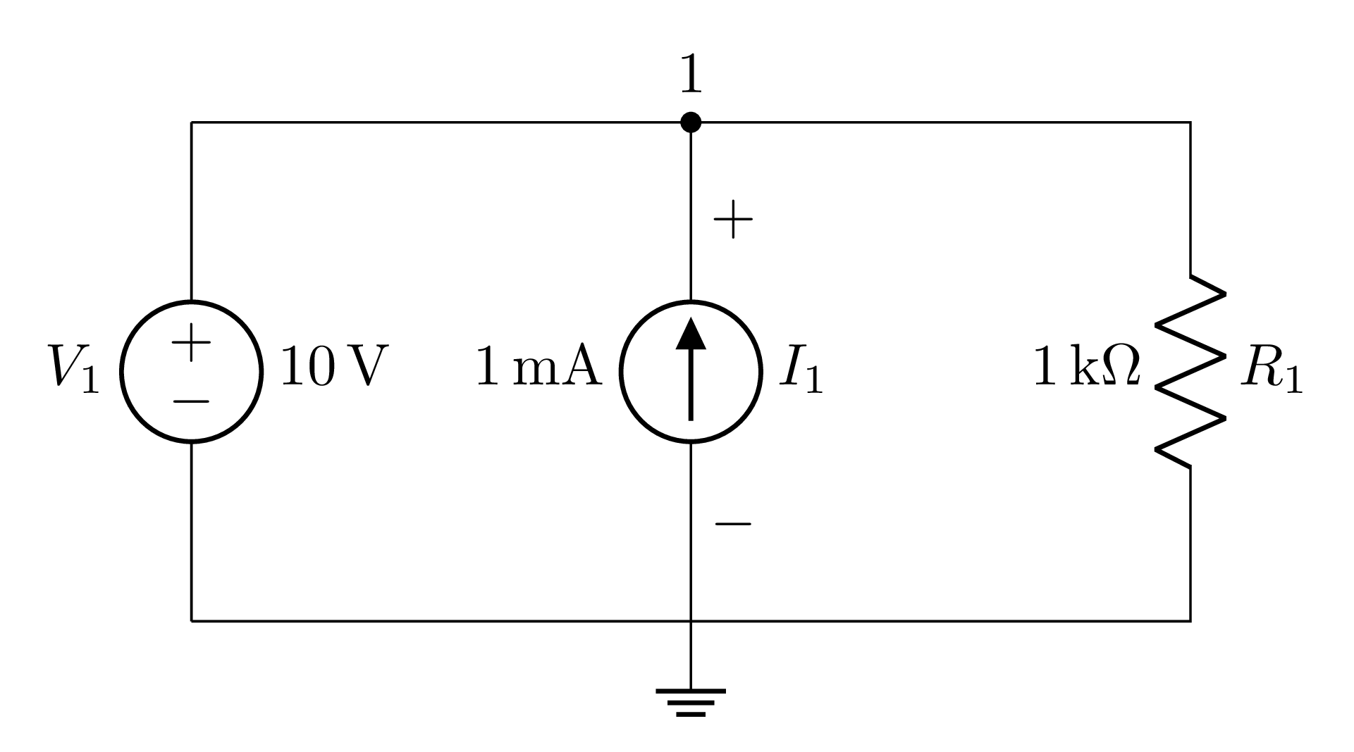
V1 1 0 10
I1 1 0 6k
R2 1 0 4k
Passive components
All passive components (resistors, capacitors and inductors) follow the same convention:
Current goes from the first node to the second
For the voltage drop, it is measured from the first node to the second, so the first one is the “positive”, and the second the “negative”
If the current is actually going from the second node to the first, the software will print that it is negative. Similarly, if the voltage drop is positive from the second node to the first, the software will also print it as a negative value.
A good example of this is the circuit below. Notice how the nodes are written in the netlist:

V1 IN 0 10
R1 IN OUT 1k
R2 0 OUT 1k
For R1, its current and the voltage drop are from IN to OUT. Since, going by the circuit, those are the directions they actually are, the software will calculate them as positive values (5 mA and 5 V). For R2 however, its current and voltage drop are from 0 to OUT, which are are opposite to their actual directions, so they will be negative (-5 mA and -5 V).
This is particularly important for energy storage components (capacitors and inductors), because, since all voltages/currents/states depend upon the capacitors voltages and inductor currents (as explained here), the order you write the nodes for these components will affect the results on every other component as well.
.STEP
When you want the difference equations for the circuit, it is recommended to provide the
time step for the software, as explained here. One of the ways to do this is to use the
.STEP command, followed by the time step, in seconds. The rules for writing this are the same ones for writing the
component values. So, if you want a time step of 1 micro second, you can write .STEP 1u,
or .STEP 1e-6.